


The Integrated Controller V series consists of seamless, scalable controllers that integrate such functions as sequence control (S), loop control (L), and computer processing (C), which have been independent so far and cover a wide range of systems, large or small. The sequence, loop, and computer functions are made possible by a single architecture, and a single engineering tool covers a system as a whole. The integrated controllers are control devices of a new generation that are integrally applicable to a wide variety of control systems, ranging from those for process automation to those for factory automation in the assembly and processing industries.
Overview
Specifications
Download Center
Training
Overview
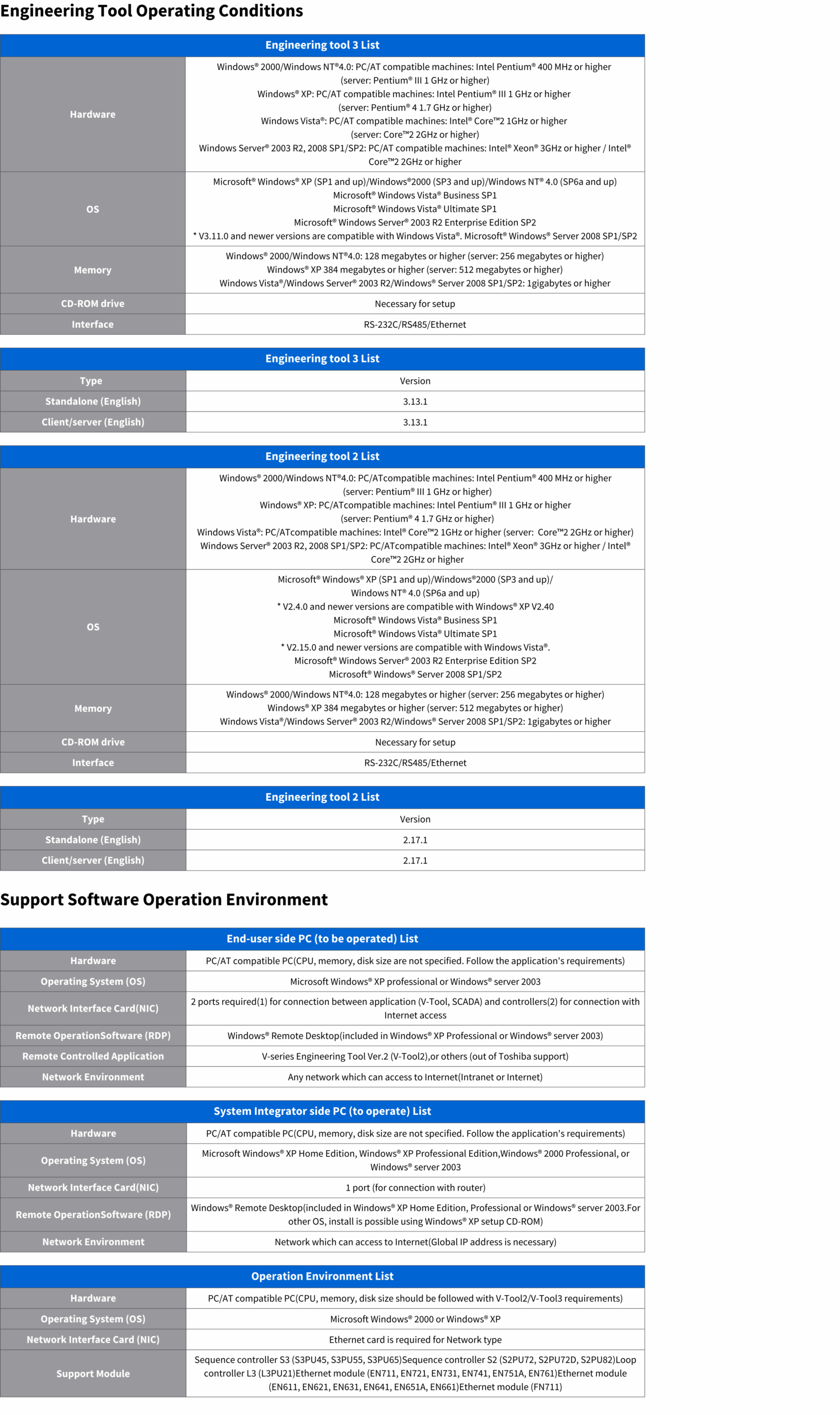
Engineering Tool
The engineering tool supports all the phases of a V-series system, from system configuration to programming, monitoring RAS information collection, and monitoring.
Engineering Tool 2 / Engineering Tool 3
Successor to the existing Integrated Controller engineering tool, version 2 and version 3 features improved user interface, added ease of operation, and higher engineering efficiency through reducing program save time. Engineering Tool 2 and Engineering Tool 3 will fully justify the true value of the Integrated Controller V series. Engineering Tool 3 supports a full-graphic editor and ST language (Structured Text) editor in addition to all the features of Engineering Tool 2.

Integrated Engineering
The engineering tools for the V series assure integrated engineering regardless of system size and control functions (sequence, instrumentation). The S and L modules can be programmed in the same program language. Apart from programming, hierarchical engineering is available from system to controller, involving network and hardware configuration and module parameter setting.

Hierarchical Programming in International Standard Language
The V series conforms to the international standard IEC61131-3 for its programming languages. The three graphical languages LD (Ladder Diagram), SFC (Sequential Function Chart), and FBD (Function Block Diagram) can be used on a single campus, thus permitting programming along the control flow. A program can be built step by step, with shared functionalities organized into function blocks, enabling hierarchical programming.

Free Variables
The local variables that can be used in a program can be defined without being conscious of data physical addresses, and the same variable name can be defined in two or more programs. Global variables shared across two or more programs follow a hierarchical structure. This structure includes variables shared within modules, between station modules, and across networks, allowing seamless data exchange regardless of system size.

Effective for System Maintenance
The engineering tool supports program monitoring, data display and configuration, module status and history tracking, system operations, and maintenance, providing an all-in-one solution for integrated engineering.


Reverse Creation Function Restores and Builds a System from Controllers
The engineering tool can fetch programs, variables, hardware configuration, and other information from the controller to restore and build a system. 1 This reverse creation function facilitates controller maintenance without program and other data in the field. In downloading data to the controller, download the data necessary for the reverse creation function. Memory consumption by the controller is greater than the actual program capacity in using this function. This function applies only to the sequence control modules S2 and S3.
Group Engineering by Client/Server
The engineering tool may be used singly and in client/server mode. This allows centralized data control by a server machine and parallel engineering with two or more client machines. This feature is effective for exclusive processing in competitive operations where two or more clients may simultaneously edit and compile a program, thus assuring efficient group engineering.
Waste-Free Transition of Engineering Data (Engineering Tool 2 / Engineering Tool 3)
Variables and other engineering data can be used by converting them into data for engineering tool 2 and engineering tool 3, using V1 Import, which is a standard component of engineering tool 2 and engineering tool 3. Therefore, the data created so far can be shifted to engineering tool 2 and engineering tool 3 without waste.
Support Software
The following V-series-related software supports the V-series life cycle from system design, debugging, and system testing through operation and maintenance.
SynchroTrend — V-Tool2 Add-In Software
The SynchroTrend is an optional software that can be added to the V-series Engineering Tool Ver.2 (V-Tool2). The SynchroTrend can gather the specified user data from V-series controllers and save it in a historical file. The data gathering is synchronized with the controller’s tasks (SS/HS/MS). Real-time trend graph display is available, as well as saved data display. The SynchroTrend supports the effective testing and commissioning of large systems.
- Applicable controller: S3PU55B Ver.2.70 or higher
- Applicable Engineering Tool: Ver.2.6.0 or higher

New Instrument FB Library — V-Tool2 Add-In Software
The New Instrument FB Library is a collection of function blocks that perform loop controls and sequence operations, which appear frequently in process control applications. By adding this library to the V-series Engineering Tool Ver.2 (V-Tool2), the programming for process control becomes highly productive and reliable.
The New Instrument FB Library has the following features: higher productivity, high-speed processing, flexible expandability, and reliable code.
Applicable controller:
- DS-type: L3PU21 Ver.1.1B or more / L2PU22 Ver.1.18 or higher
- MCS-type: L1PU11H/12H/LC511/512 Ver.2.23 or more / LC521/522 Ver.2.30 or higher
Applicable Engineering Tool: Ver.2.6.1 or higher

Permissive Fault Diagnosis — V-Tool2 Add-In Software
The Permissive Fault Diagnosis is an optional software that can be added to the V-series Engineering Tool Ver.2 (V-Tool2). The Permissive Fault Diagnosis analyzes the permissive condition (inter-lock circuit) written by LD and displays the cause signal at the permissive break.
For example, when an auto-run condition is configured by AND/OR logic of many input signals;
- Why is the auto-run condition not satisfied? — Displays only the cause contacts
- Auto-run has been broken. Which is the first fault? — Displays the first fault signal
Even if the permissive condition is configured by cascade connection of LD networks, this Permissive Fault Diagnosis can track back the networks and show the diagnostic result as a simple LD network. The Permissive Fault Diagnosis package can be effective in system commissioning and troubleshooting.
- Applicable controller: S3PU55A/55B Ver.2.76 or higher
- Applicable controller: S3PU65A Ver.3.78 or higher
- Applicable Engineering Tool 2: Ver.2.12.0 or higher
- Applicable Engineering Tool 3: Ver.3.6.0 or higher
Remote Engineering Package — Independent Package Software
The Remote Engineering Package can provide a remote maintenance environment through the Internet. Using HTTP tunneling and Windows® Remote Desktop technology provides a secure remote maintenance environment without changing the network security policy at the user site.
- System integrators can make remote maintenance networks worldwide
- Only an Internet connection is required (Port 80 and 443 are used)
- There is no need to change the firewall
- Data is encrypted using AES encryption
- Initial cost and running cost are reasonable

V-Simulator — Independent Package Software
The V-Simulator is a software that emulates S3/S2/L3DS controller operation on a PC. You can test/debug the application program without actual controller hardware. Therefore, it shortens the application program development and improves the quality.
- Emulates S3/S2/L3DS operation on a PC. It is the same operation from the V-Tool2/V-Tool3, including execution monitor, data set, etc. (some instructions are not supported)
- The Windows® API is prepared to access I/O variables. I/O simulation can be available by linking an external application software.
- V-Simulator supports LAN functionality. The HMI/SCADA can be connected with a V-Simulator through the network (Ethernet). The communication test can be done.
- Two types of connection between V-Simulator and V-Tool2/V-Tool3. (1)Stand-alone type, which contains both, and (2)Network type using two or more PCs.

LC500 Series
Multi-loop Controller LC531/LC532 is an instrumentation panel controller which supports various applications with user programs. Toshiba continuously enriches its features, excellent reliability, and user-friendliness. Simultaneously securing the compatibility of attachment to limited space, panel cut, and depth results in advanced features.
Features
High seed operations and power saving:
- Processing speed is twice of conventional models *1*2
- Power conservation of about 60%*1
*1 Compared to conventional model LC521
*2 In case the maximum registration composition is 8 PID tags
Ethernet
Construction of OIS-D/SMART supervision and control system and OIS-DS supervision and control system through PLC server and communication between single loop controller.
RS485
Support EC Bus transmission and share connection with EC300 series.
PID Control
Toshiba possesses the original hyper PID control. Advanced control system carried out easily.
Engineering
Applications of new function blocks correspond to the programming abiding by the IEC 61131-3 standard. Developments of efficient programs contribute to the reduction of development costs.
Size Line Up
There are two lines up available, size 450mm; easy replacement. Size 250mm; new compact type.

Intelligent I/O Module


TC-net I/O Module

Analog High-Speed Serial I/O System TC-net I/O


Insulated Bearings

Extended Horsepower Capability

Insulation with Wide Thermal Capability

Low Vibration
Specifications

Download Center
Training